Experimenting with the Synth Tool
Technical blog post experimenting and tweaking with Minispec's synthesis tool. I walk through some features using Verilog and Bluespec full adders as the main example.
- Introduction
- Overview
- Background
- Synth Tweaks
- Verilog Full Adder
- Bluespec Full Adder
- Verilog Wrapped with Bluespec
- Next Time
Introduction
In a series of upcoming posts, I will be presenting worked Bluespec and Verilog examples of different adders for eventual use in my RISC-V processor project. I’ll be using these adders to replace both existing adders and as components in future functional units like my integer multiplier or floating point unit.
Before all that, I need to perform some tests and set up some infrastructure. It’s no good to blindly implement components, so I spend this post experimenting with synth to identify quirks and see how it interacts with Bluespec and Verilog when we involve wrappers, which are required to import Verilog into Bluespec.
I also tweak synth to accept Verilog directly, which will be helpful to evaluate Verilog components in the same way I evaluate Bluespec components. Some upcoming posts will see whether we actually get any performance gains from implementing modules in Verilog rather than Bluespec.
This post also serves as a visual walkthrough of using the Minispec synth tool. There’s sparse documentation anywhere on its use, so I figured I may as well write some here.
Overview
I begin by discussing some tweaks I made to my fork of Daniel Sanchez’s synth tool for Minispec. These tweaks enable the rest of this post.
Then, I demonstrate the use of synth on a Verilog implementation of a full adder. I also show an example using boolean and bitwise operators where quirks in our downstream synthesis tools can create suboptimal circuits, so we should take synthesis results with a grain of salt. Because a full adder creates only a simple circuit, I also include gate-level logic circuit visualizations created using synth with several cell libraries.
I also demonstrate the use of synth on Bluespec implementations of full adders, including showing the resulting Verilog files from compilation and some strange properties that emerge when we nest Bluespec wrappers, including losing and gaining efficiency in the resulting circuits.
Afterward, I demonstrate Bluespec’s ability to directly use Verilog implementations in Bluespec designs, which will be helpful if we find Verilog implementations to be more efficient than our Bluespec ones. However, I found no performance difference with simple circuits like full adders, so that would require more testing with more complex circuits to see whether implementing in Verilog is worth the trouble. We’ll explore these things and more next time.
Background
For the past couple weeks, I’ve slowed down on technical blogging because I’ve been practicing my Verilog with the wonderful exercises on HDLBits. I’m starting to exhaust their Verilog material, so it’s about time to apply what I’ve learned. With all this practice, I’m now able to do two things:
- I can now inspect and understand the
.vthat result from compiling my.bsvfiles. Simple Bluespec modules can give us legible Verilog. With complex modules, it takes more effort but can be done, especially when side-by-side with the Bluespec source code. - I can now write
.vfiles directly and import them as IP blocks into my Bluespec designs through theimport "BVI"feature. This works best for simple modules that are done more efficiently in Verilog.
I like Bluespec for its high-level constructs and abstractions. One common criticism of the language is that the Verilog outputted by the Bluespec compiler might not be performant enough to supplant writing Verilog by hand. The trade-off is acceptable for complex top-level modules that can’t be prototyped quickly in Verilog, but in small, reusable components like adders and FIFOs, it can make sense to go lower in abstraction.
(In this post, I found no evidence with the simple full adder example that Bluespec produces any less performant circuitry than Verilog. It’s too soon to draw conclusions on this front, since we’d need more complex modules.)
This is especially the case when the optimizing compiler isn’t mature enough. There was probably a point in history when C compilers didn’t produce performant enough assembly for developers to program exclusively in C. Bluespec may very well be at that point right now with producing performant Verilog. In an ideal world, the Bluespec compiler should be able to automatically make the same optimizations a human designer would.
To understand how our Bluespec turns into Verilog, we can refer to the BSC User Guide. People interested in greater detail should check out the chapter “Verilog back end” and especially the subsection “Bluespec to Verilog mapping”, which describes how .bsv files are transformed into Verilog .v files.
You can also read the chapter “Embedding RTL in a BSV design” in the BSV Reference Guide where they discuss importing Verilog modules into Bluespec for use in the Verilog backend. As per the User Guide, the Bluesim backend is currently incapable of using Verilog directly. When we import, we’d need to use Verilog simulators or write Bluespec implementations for simulation in Bluesim. This makes it a little less convenient to import Verilog when we use Bluesim for simulation, like I currently do.
Synth Tweaks
The synth synthesis tool we use from Daniel Sanchez’s Minispec compiles our Bluespec .bsv files into Verilog .v files, then does a bunch of processing with yosys and ABC to determine our area and critical-path delay.
It’s a nicely designed tool, but I need to make a series of tweaks to make it work better for my purposes. The main change is that I’d like to be able to synthesize Verilog files directly, but I also make a bug fix and a cosmetic change. You can see my modified version on my fork on GitHub. I don’t know how widely applicable my changes are, so I don’t plan on making a pull request.
Accepting Verilog Inputs
The synth tool was built to consume Minispec and Bluespec, but internally it compiles both into Verilog .v files for synthesis with downstream tools with yosys and ABC. There might be established tools for generating area and delay numbers for Verilog designs, but I both like Minispec’s synth and I have trouble finding off-the-shelf synthesis tools. (I suspect many of them are proprietary.)
I modified synth to be able to accept Verilog modules directly for synthesis. It’s just a matter of being able to skip the Minispec/Bluespec compilation step of the synth tool and using the Verilog .v files directly.
It’s also a matter of moving the .v files in the current directory into the synthDir so that they can be consumed as needed by other modules (specified by the .use files). This is especially important for Bluespec import "BVI" statements because the .v files from the compilation will assume that the imported .v files will be available for synthesis.
When we eventually do Verilog simulation, we’ll also need to ensure that our .v files are moved to build for simulation.
Alternatives
When I was thinking about how to measure the performance of both Bluespec and Verilog modules, I briefly considered using the wrapper-only route. I wouldn’t need to modify the synth tool as long as all my Verilog modules were presented as Bluespec modules.
I decided that it would be a little too roundabout to need to wrap all my Verilog modules in Bluespec just to synthesize them. I may want to synthesize separately even before importing these modules into a Bluespec design. It’s not much trouble, but it requires writing a bit of boilerplate.
It wasn’t so hard to modify the synth program. It’s written in Python, so I just needed to read through it and figure out what to change.
Buffer Configurations
I had already tweaked my installation of synth during my processor project. During the step where the program synthesizes with three buffer configurations, one of them would suddenly require much, much, much more computation than the other two. It’s no problem for small designs, but it would take so much computation for synthesizing my L1 caches that the synthesis would crash.
To locate the issue, I looked at the different output logs from synth to see where the tool was stalling. I found that synth would generate several configurations and select the best one. synth would crash because one of these sets would stall.
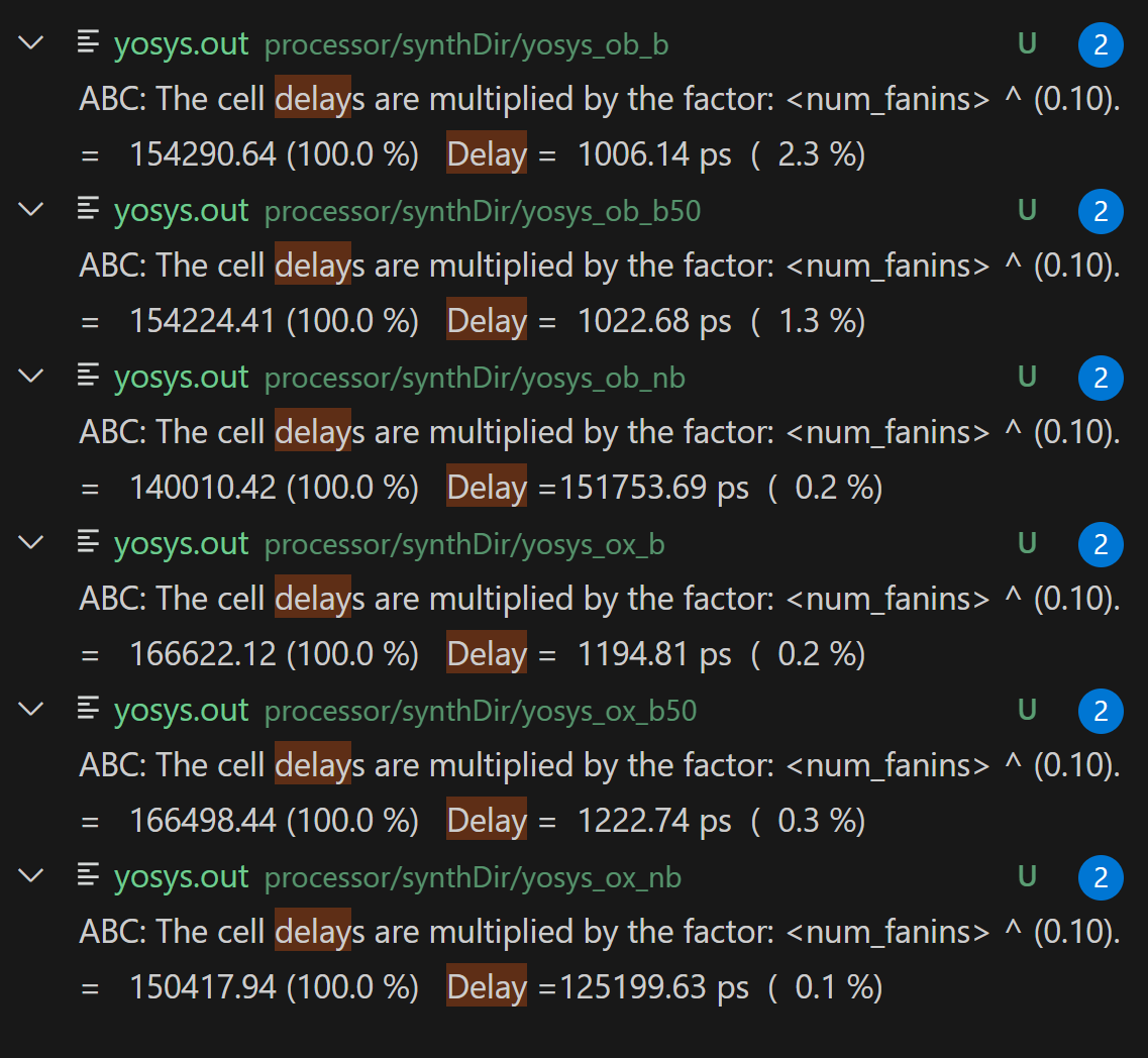
ox) and -O1 (ob) optimization parameters.I “fixed” the issue by making synth skip the configuration prone to stalling. I don’t know whether it’s a true fix because it might result in worse generated circuits for some designs. I checked it makes no difference for my full adder implementations.
SVG Tweaks
I also adjusted the color scheme of the svg generator to output dark mode circuit visualizations, just because that’s what I use for everything, including this blog.
If I was submitting a pull request, I would want to make it configurable from the command line. But because I only ever need dark mode, I just changed the color values in the svg file in synth.
Verilog Full Adder
In this section, I wanted to test out my changes to synth by synthesizing a simple full adder module written in Verilog.
I also run a little experiment with using different operators. Below, I choose to use boolean operators (e.g., &&, ||) even though I could use bitwise operators (e.g., &, |). I explain more soon.
The synth tools customarily requires us to have every module accept a CLK, which can remain unused.
module FullAdder(
    input CLK, a, b, c_in,
    output sum, c_out
    );
    always @(*) begin  // generally I would prefer always_comb in SystemVerilog
        sum = a ^ b ^ c_in;
        c_out = (a&&b) || (a&&c_in) || (b&&c_in);
    end
endmodule
With my above tweak, I can run synth FullAdder.v FullAdder to generate synthesis logs.
Basic Cell Library
Synthesizing FullAdder from file FullAdder.v as a Verilog module.
Synthesizing circuit with std cell library = basic, O1, target delay = 1 ps

Gates: 14
Area: 10.11 um^2
Critical-path delay: 51.75 ps (not including setup time of endpoint flip-flop)

Critical path: b -> sum
               Gate/port   Fanout        Gate delay (ps)  Cumulative delay (ps)
               ---------   ------        ---------------  ---------------------
                       b        3                    7.6                    7.6
                   NAND2        3                   14.3                   21.9
                     INV        1                    8.4                   30.3
                    NOR2        1                    6.1                   36.4
                   NAND2        1                    8.6                   45.0
                   NAND2        1                    6.7                   51.7
                     sum        0                    0.0                   51.7

Area breakdown:
               Gate type    Gates       Area/gate (um^2)       Area/type (um^2)
               ---------    -----       ----------------       ----------------
                     INV        4                  0.532                  2.128
                   NAND2        8                  0.798                  6.384
                    NOR2        2                  0.798                  1.596
                   Total       14                                        10.108
The synth tool includes an svg diagram visualizer for circuits made with the standard (basic) cell library. We get that by using the -v flag, e.g., synth FullAdder.v FullAdder -v.
Let’s see what this looks like.

Notice the synthesis mostly uses INV, NAND2 and a couple NOR2 gates, whereas a textbook full adder might only use NOR2, AND2, and an OR2. Modern physical design (or at least the kind that they teach in schools) preferentially uses NAND gates because they result in an overall cheaper circuit.
Boolean Quirks
By accident, I noticed there’s a quirk that happens when I use bitwise versus boolean operators. I think it must be an issue with the downstream optimization because semantically, it shouldn’t matter whether we’re using boolean operators or bitwise operators when each operand is a single bit. Indeed, we’ll see later that the downstream gate placement can vary unpredictably.
We get a different circuit when we use c_out = (a&b) | (a&c_in) | (b&c_in);, even if semantically we should get the same thing.

It’s technically up to the engineer whether this circuit is better or worse. It results in 16 rather than 14 gates, but we shave off half a ps of delay. I would probably go with the original 14-gate circuit since it’s only 0.7% faster (51.4 ps vs 51.7 ps) but 15% larger (11.704 um^2 vs 10.108 um^2).
Critical-path delay: 51.39 ps (not including setup time of endpoint flip-flop)
  Gate/port   Fanout        Gate delay (ps)  Cumulative delay (ps)
  ---------   ------        ---------------  ---------------------
          a        4                    9.8                    9.8
      NAND2        2                   12.2                   22.0
        INV        1                    7.7                   29.7
       NOR2        1                    6.3                   36.0
      NAND2        1                    8.6                   44.6
      NAND2        1                    6.8                   51.4
        sum        0                    0.0                   51.4

  Gate type    Gates       Area/gate (um^2)       Area/type (um^2)
  ---------    -----       ----------------       ----------------
        INV        4                  0.532                  2.128
      NAND2       10                  0.798                  7.980
       NOR2        2                  0.798                  1.596
      Total       16                                        11.704
In some cases, we can use the --retime flag with synth to re-generate a more efficient and logically equivalent circuit. For whatever reason, it didn’t work with this one.
Extended Cell Library
We can also get different results with different cell libraries. I generally stick with basic, but there’s no reason why we can’t use the other ones. They just give us different gates. The main difference with this library for the full adder is that we gain access to NAND3 gates, which we use for c_out.
I synthesize using the -l option with a cell library name, e.g., synth FullAdder.v FullAdder -l extended -v. I trimmed the following log for conciseness.
[Extended]
Critical-path delay: 49.98 ps (not including setup time of endpoint flip-flop)
  Gate type    Gates       Area/gate (um^2)       Area/type (um^2)
  ---------    -----       ----------------       ----------------
        INV        3                  0.532                  1.596
      NAND2        8                  0.798                  6.384
      NAND3        2                  1.064                  2.128
      Total       13                                        10.108

Multisize Cell Library
Here, we use a few different gates other than NAND2, but we still stick mostly with NAND2.
[Multisize]
Critical-path delay: 48.84 ps (not including setup time of endpoint flip-flop)
  Gate type    Gates       Area/gate (um^2)       Area/type (um^2)
  ---------    -----       ----------------       ----------------
     INV_X1        1                  0.532                  0.532
   NAND2_X1        5                  0.798                  3.990
   NAND3_X1        1                  1.064                  1.064
     OR2_X2        1                  1.330                  1.330
   XNOR2_X1        1                  1.596                  1.596
      Total        9                                         8.512

Full Cell Library
We can synthesize with a more diverse full cell library, but synth doesn’t currently support generating circuit diagrams for it. It’s probably just a matter of adding in the svg components for all the different gates.
[Full]
Critical-path delay: 47.63 ps (not including setup time of endpoint flip-flop)
  Gate type    Gates       Area/gate (um^2)       Area/type (um^2)
  ---------    -----       ----------------       ----------------
    AND2_X1        1                  1.064                  1.064
     INV_X1        1                  0.532                  0.532
   NAND2_X1        2                  0.798                  1.596
   NAND3_X1        1                  1.064                  1.064
    NOR2_X1        1                  0.798                  0.798
   OAI21_X1        2                  1.064                  2.128
     OR2_X2        1                  1.330                  1.330
      Total        9                                         8.512
Bluespec Full Adder
In this section, I wanted to synthesize a simple Bluespec full adder and inspect the resulting Verilog files and synthesis outputs. I also wanted to test whether the choice in boolean or bitwise operators made a difference in the resulting circuit like it did for the Verilog full adder.
Implementing in Bluespec gives us some more design choices. Bluespec’s richer type system distinguishes between booleans Bool and bits Bit#(1). Typically, I would prefer the bitwise implementation because semantically, the bits of a full adder generally represent parts of larger bit vector operands and sums.
But like in the above Verilog case, there may be performance implications in our downstream tools for using boolean versus bitwise operators. Until such a time that the performance quirk gets optimized out, I need to weigh the trade-offs between a more performant circuit with the boolean implementation, versus semantic accuracy with the bitwise implementation.
It may even turn out that it’s easier to work with the bitwise implementation, or that the quirk only appears when we’re synthesizing the full adder directly and not as a component. Because it’s only two gates, I’m leaning toward using the bitwise implementation for future components. In this section, we test both.
Switching between boolean and bitwise in Bluespec is a little trickier than in Verilog because I need to not only change the operators, but also the types. If you want the bitwise implementation, just replace Bool with Bit#(1) and the operators !=, &&, and || with ^, &, and |.
typedef struct {
    Bool sum;
    Bool c_out;
} FullAdderResult deriving (Bits, Eq);

interface FullAdder;
    method FullAdderResult exec(Bool a, Bool b, Bool c_in);
endinterface

(* synthesize, always_enabled, no_default_reset *)
module mkFullAdder(FullAdder);
    method FullAdderResult exec(Bool a, Bool b, Bool c_in);
        return FullAdderResult {
            sum : a != b != c_in,  // no logical xor
            c_out : (a&&b) || (a&&c_in) || (b&&c_in)
        };
    endmethod
endmodule
For such a simple design, the Bluespec generates identical circuits as the corresponding (bitwise or boolean) implementations in Verilog, so I don’t bother reproducing the synthesis logs.
There are some minor differences in the visualizations:
- The ordering of the operands (doesn’t matter in a full adder),
- The
{sum, c_out}are bused into a 2-bit output, and - If we don’t include
no_default_resetandalways_enabledattributes, there would be an unusedRST_NandRDY_execdriver on the visualization.- In the following visualizations, I omitted the attributes, so they don’t correspond exactly with the above excerpt. So, imagine there’s only the
synthesizeattribute.
- In the following visualizations, I omitted the attributes, so they don’t correspond exactly with the above excerpt. So, imagine there’s only the
Notice that the operands are prefixed with exec. That’s because this whole circuit corresponds to the exec method of the module. We’d have a different looking circuit if we had other methods or rules to synthesize.
Bitwise Implementation

Boolean Implementation

You may also notice the unused RDY_exec. We can remove it by adding the always_enabled attribute next to the synthesize attribute, and it’ll be gone. It wouldn’t change the resulting circuit’s delay or area, since the unused RDY_exec signal gets optimized out anyway.
We could further remove the unused CLK and RST_N ports with the attributes no_default_clock and no_default_reset. We won’t remove the clock since the synth tool requires a clock port to synthesize a module. But there’s no reason why we can’t remove the RST_N.
I add the no_default_reset and always_enabled attributes into the Bluespec excerpt above, but I’ve kept the drivers in the visualizations so you can see what I’m talking about.
Resulting Verilog Files
For the above visualizations, I didn’t add any attributes other than synthesize. To generate the following Verilog, I added the always_enabled, no_default_reset attributes (just like the Bluespec excerpt above).
These Verilog files are generated by the Bluespec compiler for use in downstream tools like synth, other Verilog synthesis tools, or Verilog simulators.
Note that I present these files in the reverse order as the visualizations above.
Boolean Implementation
The compiled Verilog for such a simple circuit as the boolean implementation of the full adder is very legible, though it uses Verilog 1995 style declaration. The calculation of the carry also uses a boolean simplification.
module mkFullAdder(CLK,

		   exec_a,
		   exec_b,
		   exec_c_in,
		   exec);
  input  CLK;

  // value method exec
  input  exec_a;
  input  exec_b;
  input  exec_c_in;
  output [1 : 0] exec;

  // signals for module outputs
  wire [1 : 0] exec;

  // value method exec
  assign exec =
	     { (exec_a != exec_b) != exec_c_in,
	       exec_a && (exec_b || exec_c_in) || exec_b && exec_c_in } ;
endmodule  // mkFullAdder (boolean implementation)
Bitwise Implementation
Unfortunately, the bitwise implementation doesn’t result in as legible a Verilog file. The compiler makes liberal use of internal signals and wire instantiations.
There’s no boolean simplification like above. I would’ve originally guessed the lack of simplification is why the design costs more gates, but we saw earlier that this happens even when we write directly in Verilog, and we’ll see later that we sometimes regain efficiency with some strange wrapping.
module mkFullAdder(CLK,

		   exec_a,
		   exec_b,
		   exec_c_in,
		   exec);
  input  CLK;

  // value method exec
  input  exec_a;
  input  exec_b;
  input  exec_c_in;
  output [1 : 0] exec;

  // signals for module outputs
  wire [1 : 0] exec;

  // remaining internal signals
  wire x__h20, x__h37, x__h40, x__h52, x__h54, y__h53, y__h55;

  // value method exec
  assign exec = { x__h20, x__h40 } ;

  // remaining internal signals
  assign x__h20 = x__h37 ^ exec_c_in ;
  assign x__h37 = exec_a ^ exec_b ;
  assign x__h40 = x__h52 | y__h53 ;
  assign x__h52 = x__h54 | y__h55 ;
  assign x__h54 = exec_a & exec_b ;
  assign y__h53 = exec_b & exec_c_in ;
  assign y__h55 = exec_a & exec_c_in ;
endmodule  // mkFullAdder (bitwise implementation)
Wrappers around Bluespec
In Bluespec, we can wrap a module’s implementation in another module. It looks like this:
(* synthesize *)
module mkFullAdderWrapper(FullAdder);
    FullAdder _adder <- mkFullAdder;
    return _adder;
endmodule
The underlying Verilog instantiates the inner module and connects its ports with the external module’s ports. It’s all done in wires, so we might expect no difference in the resulting circuit.
In this section, I investigate whether there’s any overhead in synthesizing wrapped Bluespec. For thoroughness, I check nested wrappers too, like when we wrap a wrapper.
Losing Efficiency
When I experimented using synth, I saw using a wrapper can (but might not) affect the resulting circuit. Wrapping our boolean implementation gives us a 16-gate circuit (like with the bitwise implementation) instead of our original 14-gate circuit.
We might chalk this up to overhead from wrapping, but we shouldn’t be getting any overhead from just connecting wires.
It must do with the downstream tools. Similar to the boolean versus bitwise case, there’s something preventing the synthesis tool from optimizing the resulting gate placements.
module mkFullAdderWrapper(CLK,
			  RST_N,

			  exec_a,
			  exec_b,
			  exec_c_in,
			  exec,
			  RDY_exec);
  input  CLK;
  input  RST_N;

  // value method exec
  input  exec_a;
  input  exec_b;
  input  exec_c_in;
  output [1 : 0] exec;
  output RDY_exec;

  // signals for module outputs
  wire [1 : 0] exec;
  wire RDY_exec;

  // ports of submodule _unnamed_
  wire [1 : 0] _unnamed_$exec;
  wire _unnamed_$exec_a, _unnamed_$exec_b, _unnamed_$exec_c_in;

  // value method exec
  assign exec = _unnamed_$exec ;
  assign RDY_exec = 1'd1 ;

  // submodule _unnamed_
  mkFullAdder _unnamed_(.CLK(CLK),
			.exec_a(_unnamed_$exec_a),
			.exec_b(_unnamed_$exec_b),
			.exec_c_in(_unnamed_$exec_c_in),
			.exec(_unnamed_$exec));

  // submodule _unnamed_
  assign _unnamed_$exec_a = exec_a ;
  assign _unnamed_$exec_b = exec_b ;
  assign _unnamed_$exec_c_in = exec_c_in ;
endmodule  // mkFullAdderWrapper
I also tried adding a second layer of wrapper. If the first wrapper reduced performance (for unknown reasons), maybe a second wrapper would reduce performance even more.
(* synthesize *)
module mkFullAdderWrapper2(FullAdder);
    FullAdder _adder <- mkFullAdderWrapper;
    return _adder;
endmodule
But we didn’t lose performance! The resulting circuit is back to 14-gate, which is the same as the unwrapped boolean implementation.
At first, I found that wrapping three times gets us the 16-gate, and wrapping four times gets us the 14-gate. There was a cycle of gaining and losing performance, even when the Verilog for each layer of wrapper was practically identical to the last.
(When I went back to verify, the results changed, which I soon discuss.)
Gaining Efficiency
I ran the same wrapper experiment with the bitwise implementation. If synth gave us the 16-gate for bitwise, maybe we’d get 16-gate no matter the wrapper.
Surprisingly, adding a wrapper actually gave us the 14-gate circuit. The tool was telling us that our full adder was more performant with a wrapper. Adding more wrappers resulted in several 14-gate, and one 16-gate. There didn’t seem to be any pattern.
This is only if we don’t specify no_default_reset; otherwise they’re all 16-gate. (Don’t ask me why.)
Nondeterminism
The day after, I found that each arrangement of wrappers didn’t necessarily result in the same circuit as the day before. I don’t believe I really changed anything, so I wonder if it’s a nondeterministic bug.
It’s interesting that the mere action of adding more wrappers can be enough to massage the synthesis tool into giving us the more efficient 14-gate circuit. It shows that the downstream bug isn’t just restricted to the kind of operator you use.
The main takeaway is that we should be wary about how much stock we put into our synthesis numbers. Even for a circuit as simple as a full adder, there seems to be inefficient gate placement. For much more complex designs, we should consider the synthesis numbers to be only approximate, at least until we secure more sophisticated downstream synthesis tools.
Verilog Wrapped with Bluespec
Wrapping Bluespec modules in Bluespec can be useful, but the real use comes with wrapping other languages in Bluespec.
Bluespec offers support for bindings between Bluespec modules and Verilog modules (going down in abstraction, at the cost of productivity) or Bluespec functions and C functions (going up in abstraction, at the cost of performance).
For us, I’m focusing on wrapping Verilog because it might allow us to write more performant components to use in our Bluespec, like adders.
According to the BSC User Guide:
Using the
import "BVI"syntax, a designer can specify that the implementation of a particular BSV module is an RTL (Verilog or VHDL) module, as described in the BSV Reference Guide. The module is treated exactly as if it were originally written in BSV and then converted to hardware by the compiler, but instead of the.vfile being generated by the compiler, it was supplied independently of any BSV code. It may have been written by hand or supplied by a vendor as an IP, etc.
The main thing I’d like to see is whether the synthesis of a Bluespec-wrapped Verilog module is identical to a Verilog module synthesized directly. Given the above description, it should be, since it’s exactly what we practiced by playing with synth and Bluespec-wrapped Bluespec.
Let’s take our Verilog full adder and wrap it in Bluespec. Remember that each of the boolean implementations, in Verilog and in Bluespec, resulted in a 14-gate circuit. But with the capriciousness of the downstream synthesis, I would accept a 16-gate circuit too. This is especially true because we got 16-gate circuits from wrapping implementations that would’ve given us 14-gate circuits.
An import "BVI" statement also requires us to declare the mappings between the Bluespec interface and the Verilog ports. I’ve modified my Verilog full adder to output {sum, c_out} as a single reg [1:0] to be consistent with my Bluespec exec method, which packs the two values together. In Bluespec, FullAdderResult is a struct, but we implicitly pack/unpack to bits as necessary when we’re working with foreign modules.
module FullAdderVerilog(
    input CLK, a, b, c_in,
    output [1:0] out
    );
    always @(*) begin
        out[1] = a ^ b ^ c_in;
        out[0] = (a&&b) || (a&&c_in) || (b&&c_in);
    end
endmodule
import "BVI" FullAdderVerilog =
module mkFullAdderVerilog(FullAdder);
    method out exec(a, b, c_in);
endmodule
We can’t directly synthesize foreign modules, but we can wrap them and synthesize the wrapper.
(* synthesize *)
module mkFullAdderVerilogWrapper(FullAdder);
    FullAdder _adder <- mkFullAdderVerilog;
    return _adder;
endmodule
After synthesis, I found there’s no overhead to wrapping the Verilog, but the the same quirks from wrapping Bluespec reappeared to give us either 14-gate or 16-gate circuits. We should be good to go in terms of embedding Verilog into our Bluespec designs.
The main drawback of this is that while importing Verilog is fine for using the Verilog backend for Bluespec (e.g., to run simulations with Verilog tools), it doesn’t work for using the Bluesim backend, which requires all modules to be implemented in Bluespec and compiled into .ba files. We would need to either re-implement the Verilog modules in Bluespec with conditional compilation, find a Verilog simulator, or not use Verilog implementations at all.
If using the Bluespec-recommended method of conditional compilation, we need to be extra careful that our Verilog implementation of a module is cycle-equivalent to our Bluespec implementation of that same module. Otherwise, we may run into trouble with correctness when we simulate with Bluesim and find our results to be different than our results in, say, Vivado. However, I think whatever can be implemented in Verilog can usually be implemented more easily in Bluespec.
If it turns out that implementing in Verilog gives us no benefit over implementing in Bluespec, then I might just stick with Bluespec implementations for use in Bluesim. The full adder example gave no evidence of greater overhead in Bluespec, so at least it’s clean enough for simple modules.
Next Time
This time, we tweaked synth to work better for our goals, and we did some investigation on the interplay between Bluespec, Verilog, and the synth tool.
Next time, we can see about implementing adders in both Bluespec and Verilog, which synth allows us to quantitatively evaluate. For correctness, we’ll check against the built-in + operator (it looks like Bluespec’s + just wraps around Verilog’s +) as we implement a simple ripple-carry adder and several types of carry-lookahead adder.
As we implement adders, I’ll continue to evaluate synthesis differences between Bluespec and Verilog. If performance permits, we might end up not actually needing to use any Verilog implementations in our processor, allowing us to maintain a strictly Bluespec code base.
We’ll see about using these adders later on in our multiplication unit and in other places.