Mini-Eclipse
Overview
I designed and built the Mini-Eclipse as a 2D cable robot system to get the Sun out of my eyes by following and blocking the Sun through my dorm room window. It can be thought of as a smart window blind just big enough to cover the Sun but leaving the rest of the sky visible.
I walk through the theory underpinning the positioning of the Sun blocker and the motor commands to get it there.
I also discuss the software I wrote, including the Python simulation for verifying positioning and the C++/Arduino for motor control and the user interface and scheduler.
I discuss the hardware I built or used for the project, including the physical setup, details for specific parts, and some lessons I learned.
This project was also my submission to the MIT ProjXpo for Winter 2023, where I exhibited the project at a booth for a day.
Unfortunately, I don’t have much video because I didn’t have a mind for actually documenting the project until I had already disassembled the project and moved out of my dorm room. However, I do have a video of an early test moving the blocker across a “horizontal” line.
You can see some of the code on GitHub (eclipse for the C++, py for the Python). The code is incomplete with respect to running the Mini-Eclipse routine on the hardware, but works fine for exhibition mode.
If there’s anything that’s unclear or that you would like to hear more about, contact me on Signal or drop me an email and we can chat.
Background
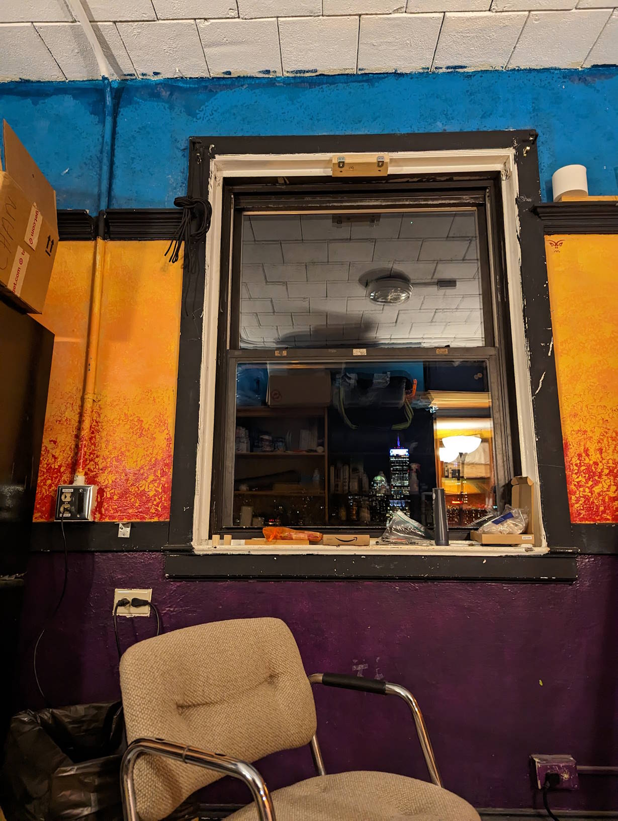
I had the fortune of having a south facing window for my last two years at MIT. I appreciated the riverside view, the wide-open sky, and the plentiful sunlight during the winter months.
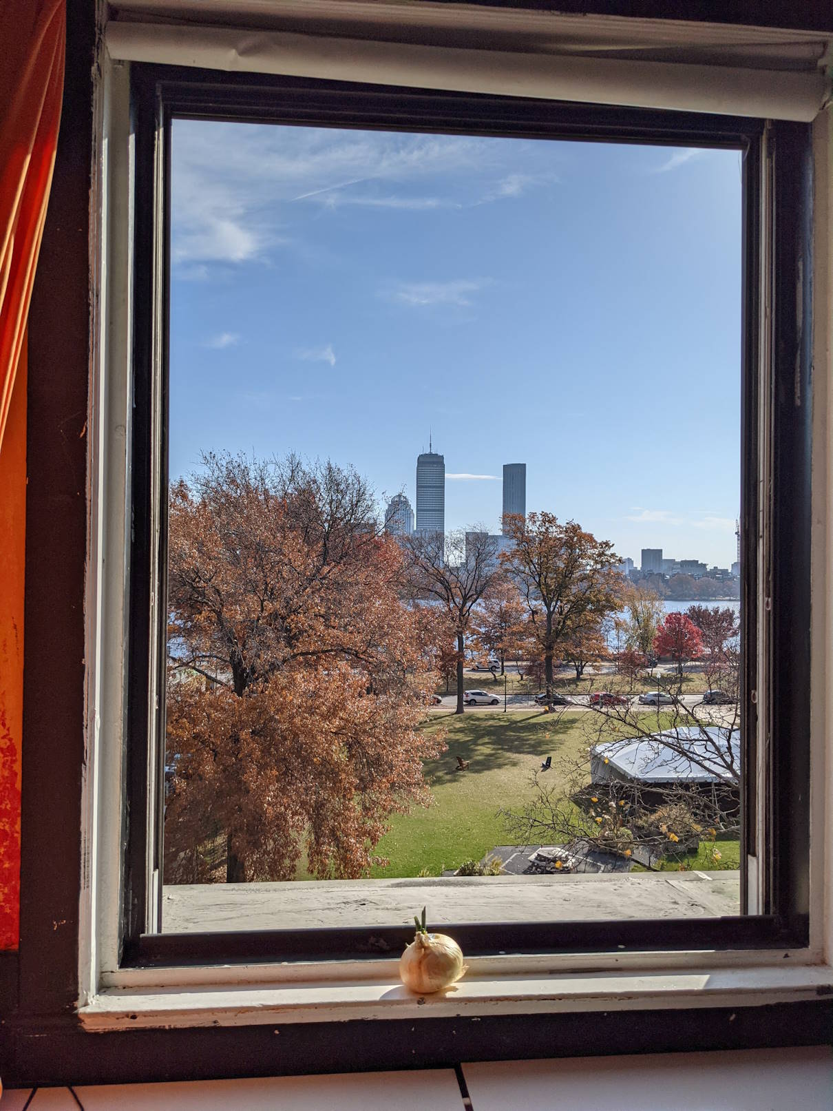
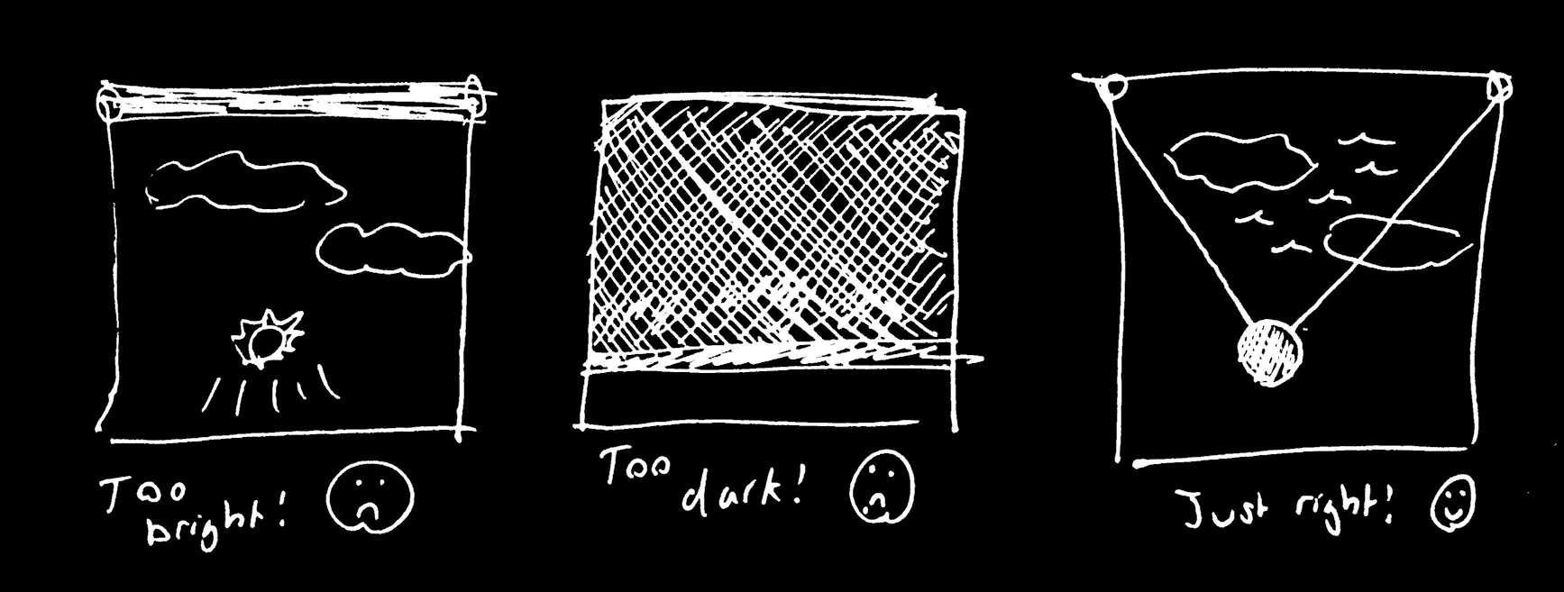
One flaw of the window was that it had major Sun glare on most winter days. Because of Boston’s high latitude, the Sun goes as low as 25-30 degrees in the sky from December through January. Great for plants, but less great for a person living in the room. My couch and desk faced the window to take advantage of the view, but the glare made them unusable in winter unless I pulled the blind down.
The blinds provided in my dorm were blackout blinds that roll from the top down, and it felt like a waste to cover up such a beautiful sky for so much of the day, especially during the wintertime when we get less sunlight anyway.
What if I could cover up just the Sun? The Mini-Eclipse was an attempt to make a system that would let me to have it both ways: to have a beautiful winter view and avoid Sun glare.
Theory
Working through the logic saves us development time since it’s cheaper to iterate on pen-and-paper than it is to iterate on Python or, even worse, C++. That said, I did end up needing to bounce around between pen-and-paper, software, and even hardware because of assumptions I made that ended up not working out.
If I get the time and inclination, maybe I’ll replace the shoddy hand-drawn diagrams with cleaner diagrams mocked up in Figma or something similar.
Positioning
How do we know where the Sun is?
To determine the Sun’s location, we don’t actually use a camera or sensors or anything of that kind. Its path is a known function of location and time, and there are many calculators available online that give the Sun’s location for a given latitude, longitude, and time. We typically encode the position of the Sun as a pair of angles in the horizontal coordinate system.
Because I built the system for my dorm room, I hardcoded my location into the software. We can then view the Sun position just as a function of time.
How do we decide where to put the blocker on the window?
We need to find the point on the window directly in between the Sun and the viewer.
The first step here is to establish a coordinate system and figure out what variables we know. I set the upper left corner of my window as the origin of my system. An (x, y) pair defines a point on the window, where 0 <= x <= width from the left edge of my window and 0 <= y <= height from the top edge of my window.
The positioning of the viewer affects the blocker, so we need to use the viewer’s position in Cartesian distance from the origin of the system, (v_x, v_y, v_z). Let’s not worry about signs for now.
And remember, we have the horizontal coordinates for the Sun, (theta_azimuth, theta_altitude). A more rigorous derivation would need to define the zeros for these angles, but as long as we’re careful we can cross that bridge when we get to it. Altitude is zero at the horizon, but I don’t remember if I set zero azimuth as pointing left from the window or perpendicular from the window.
With all this, we can take the viewer position and Sun position and calculate for each of (x, y). We can get each component by calculating purely in that dimension, then glue our results together. Let’s try one dimension.
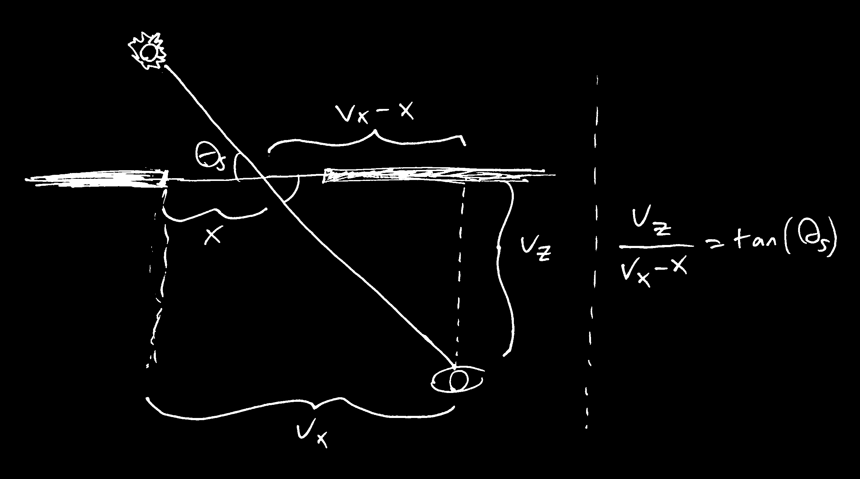
x is a function of the viewer’s distance from the origin (v_z away from the window, and v_x horizontal offset) and the relevant solar angle (here theta_s for azimuth). The key formula is taken from trigonometry. We can solve for x because the equation has four variables and we have three knowns. The result is x = v_x - v_z * cot(theta_s) Remember to also check whether the blocker’s outputted position is within bounds of the window.One simplification we’re making to ease calculations is to assume the Sun, the blocker, and the viewer are both point-like. In reality, the Sun has a width from Earth of about 0.55 degrees, so the blocker must be at least that angular size. The further away the viewer sits from the blocker, the larger the blocker will need to be.

Further, we’re assuming one viewer. Most people will have two eyes, so the blocker should be able to accommodate both. An easy solution is to make the blocker big enough that you won’t have to worry about it. The precise solution is to make a pair of circles whose centers are separated by a distance equal to the distance between the viewer’s eyes, and whose sizes are the same apparent size as the Sun. At ten feet away, that would only be about 1.15 inches wide. On a first go, let’s use the easy solution.
How do we physically place the blocker at a position?
People familiar with CNC might choose to set the system on rails or something similar. But I opted for a string suspension system, similar to a cable robot. The benefit is that I only need to mount the system at the top of my window, so there’s a very small footprint.
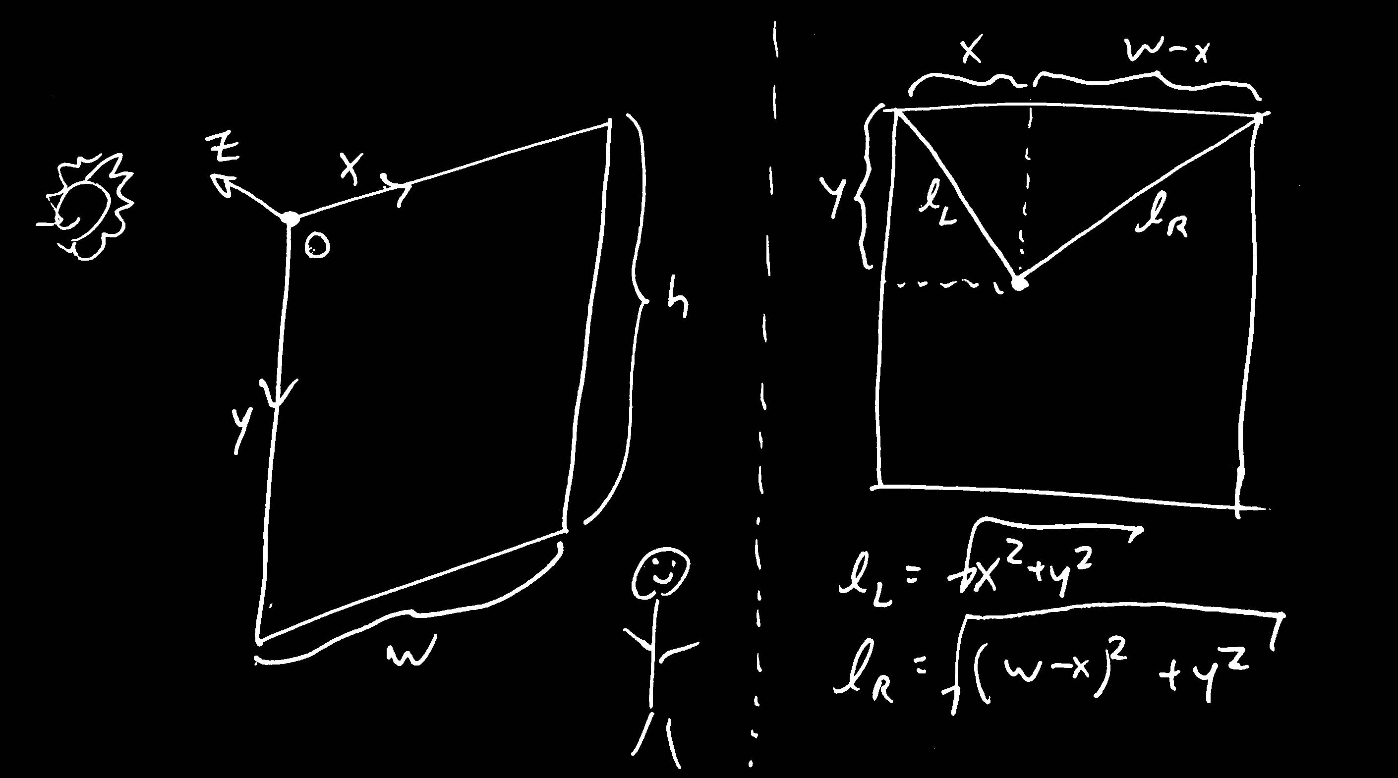
l_L and l_R that will suspend our blocker from the top two corners of the window, which are simple functions of x and y (given a constant window width)There’s only one way that I know how to control the length of string using a motor, and that is to use spools. Each motor can extend the string by rotating its spool in one direction, then retract it by rotating in the other. To connect our calculation for the positioning with our calculation for the string, we need to decide on our model for the spool.

l_L = sqrt(x^2 + y^2). For non-giant spools, that’s a no-brainer approximation to make. But if we want to be very precise, the string’s length is actually not the same as the radial distance, but rather l_tangent = sqrt(l_radial^2 + spool_radius^2). Further, the string loses or gains up to a quarter turn of length (l_arc) depending on the position of the blocker, where it goes longer vertically below the spool and shorter horizontally away from the spool. For us, that’s a very small error, especially since the spool I used was an inch in diameter. I wasted a lot of time trying to gain that precision because I didn’t pay enough attention to assessing the difference first. That’s premature optimization for you.Isn’t that interesting? We treat the spool as point-like so we can pretend the string comes from the center of the spool, simplifying our coordinates. But we also know the spool has some diameter, because we need to find the number of rotations of the spool per inch of string. This discrepancy introduces some (acceptably small) error into our system.
Control
Now that we’ve established where to put the blocker and that we suspend it with strings, let’s figure out how to control its movement. We know we can spin the motors by a specific number of rotations to induce a specific amount of string movement. Our Arduino should be capable of moving to the appropriate position as long as we command it to go to the correct angular position according to n = length / (2 * PI * R)
Let’s take a moment to think about controlling the speeds of the motors.
Unlike linear rails in a conventional CNC system, our strings (and forces) aren’t orthogonal. The extension and retraction of either string affects the blocker’s (x, y) position. We must treat them together when considering motion along Cartesian coordinates.
Further, the directions of the forces change depending on the position of the blocker relative to the two anchors.
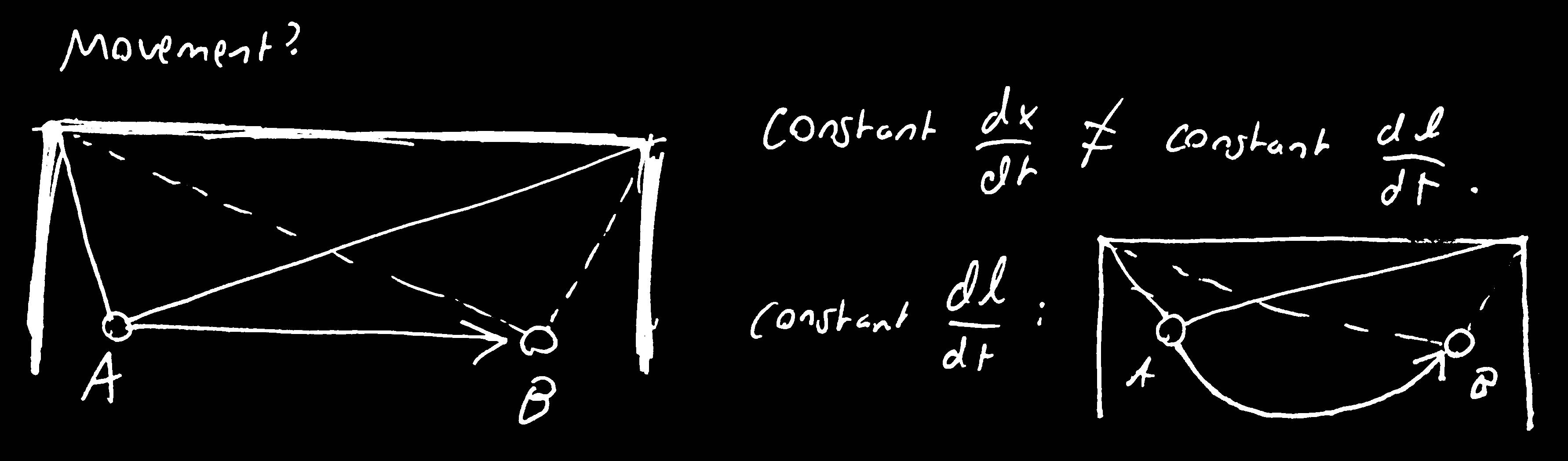
If we want the blocker to move in a straight line in Cartesian coordinates, the robust move is to write the differential relationships between Cartesian movement and the string movements and add in our constraints. We want the Cartesian movement to be in a straight line, so dx/dt and dy/dt are both constant and the speeds are such that they finish at the same time. Our Arduino might not be able to compute the precise speeds, so we might want to approximate the formulas and only change speeds at given steps. Another way is to interpolate the points between A and B, but you’d need to check that the grid speed is constant.
I didn’t end up doing the math because we don’t need this level of precision for the Mini-Eclipse goal. A straight line is elegant if we’re focusing on the cable robot as its own thing, but the Mini-Eclipse system really only moves very slightly every few minutes. It’s no big deal if the line is straight or not.
That’s one of the issues I had with this project; some of the goals for making a good cable robot aren’t aligned with the goals for making a good Mini-Eclipse. I tried to optimize in both directions and it didn’t work out great.
Instead, I just kept the string speeds constant and finishing at the same time. That’s smooth enough for Mini-Eclipse.
Software
Simulation
We’ve established the theory, but is it any good? Before writing any proper code for the microcontroller, I first modeled the system in Python.
It was essentially a straight-forward implementation of the theory behind positioning. I wrote the simulation from my family’s home during winter break, but I set all the parameters to be the same as my dorm room window. The effect is that the output image should be identical to if I ran the system in-person.
One detail is that the window’s orientation adds an offset to the Sun’s azimuth angle because our window isn’t aligned on a horizontal grid (if the window isn’t perpendicular to the ground, then we need to adjust the altitude too). I got my window’s orientation without needing to measure it myself. MIT’s campus runs on a grid, and my window’s line of sight was exactly perpendicular to the Charles River. I knew that the Infinite Corridor was exactly parallel to the Charles River, so I just worked my way from the angles used for MIThenge, where the Sun shines directly down the corridor twice a year. I checked my work using an online solar calculator.
Rather than hand coding the equations for figuring the Sun position, I used the Python library suncalc. I also used matplotlib.pyplot to make the following visualizations.
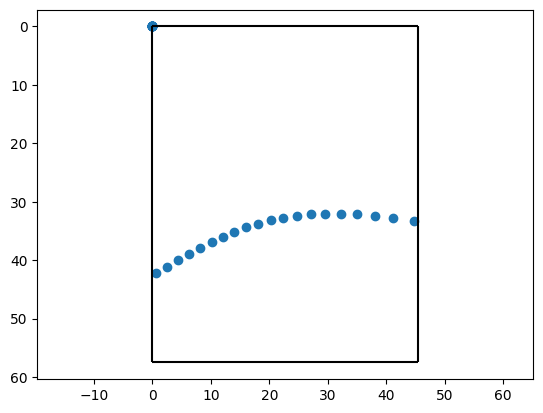
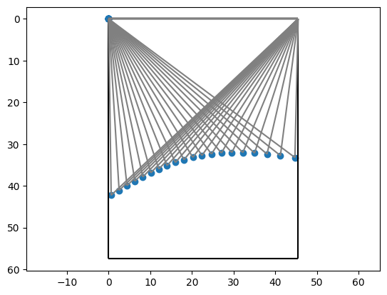
Even though the theory seemed sound, it was encouraging to see a plausible Sun path on the simulation. It meant I could move forward with physically implementing the system.
Arduino Control
To control the physical system, I wrote some Arduino/C++ code to model the strings and send appropriate motor commands to my stepper motor drivers.
I originally started with a home-cooked solution that wrapped around the official Stepper Arduino library, but it was too basic to do the position tracking that I wanted to do. I transitioned to using the AccelStepper library instead, which already supported some of the functionality I was implementing.
The main part of implementing the control was reliably translating from Cartesian (or grid) coordinates, which is how we think about blocker position, into string or step coordinates that the motors can understand. I wasted a little time trying to get a little extra precision in the spool model, but otherwise it was a straightforward application of our earlier control theory.
One subtlety that comes with physically running the system is that torque becomes unacceptably high when we’re too close to the spools. When the string angle approaches the horizontal, it requires a high amount of torque from the motors to resist the torque from gravity. To solve for this, my y = 0 isn’t actually at the vertical level of the motors, but offset to be a good distance below. I believe I chose something around 20 inches. If we want coverage of the whole window including the top portion, we would need to raise the system a foot or two above the top edge of the window.
Once I had a good way of translating between string and grid coordinates, I could think in Cartesian coordinates but have the control system think in string lengths. I tested this system thoroughly by hand, but I didn’t see a way of running any good automated tests other than eyeballing the results. This system would receive commands from our interface (more on that later), and it would serve as the physical support for the Sun tracking routine.
I wrote some wrapper code to model the window Sun angles calculation using the Overgrow C++ Sun tracking code, but I didn’t have time to finish implementing the Sun tracking component to the degree where it would give me a coordinate pair on the window as a function of time. Some of that effort instead went to polishing my project for the exhibition.
As a callback to our section on control, here’s a video of what happens when we try to get the blocker to run in a straight line. I could also imagine writing a simulation that allows us to simulate the blocker movement according to our string speed policy.
Interface
I wrote a simple parser for commands that I could send to the system via the Arduino Serial. Some of these are to calibrate the system (e.g., time, set origin, string lengths).
With the commands, I could make it go to particular Cartesian coordinates (e.g., go 5 5). Behind the scenes, it was doing all the calculations we discussed in the theory section on control. It was nice seeing the system go between specific points as if it was built on a grid instead of two spools of string. I could also make it change string lengths with commands like inch 20 -10, where the left motor extends by 20 inches and the right motor retracts by 10.
One of the interface features I’m most pleased with was being able to recalibrate the system’s string lengths. There’s no way for the Arduino to directly measure the string lengths itself, so I had a tape measure ready every time the spools were messed with. By inputting the lengths of each string to the blocker, I could remind the system where it is and it can perform the calculations necessary to move around on the Cartesian grid again. Otherwise, it could move strangely.
In preparation for the Mini-Eclipse portion, I had a command settime, e.g., settime 2023.08.16 22:08 -5, that would give the system its time because it didn’t have Internet access. Once given, it could keep track with its internal timer. We needed this part for the Mini-Eclipse to know the Sun’s position at a given time.
Unfortunately, I didn’t add a command to change the position of the viewer. This was in part because I hadn’t yet implemented the notion of a viewer, as I mentioned when discussing the Arduino control. The most likely way I would’ve implemented it would be a 3D Cartesian measurement from the system origin. A fancier way to reduce measurement time would be to encode several likely positions (couch left, couch right, desk, etc.) and then permit offsets from there.
An important piece of the interface is the scheduler. The principle behind it is that we give either commands or positions to be executed at particular times or at particular intervals. I used this heavily in exhibition even though I didn’t fully set up the Sun tracking.
If I had finished setting up the blocker calculation for the Sun, it would’ve only required a bit of glue code to configure a schedule that commands the blocker to that position every few minutes. It could either perform the calculation every time or have it precomputed from when the system spun up.
Hardware
There’s a blurry line between material covered in the Arduino control section and this section on hardware because the two are intertwined. I had never worked on a project with motors before, so this was new to me and one of the toughest parts.
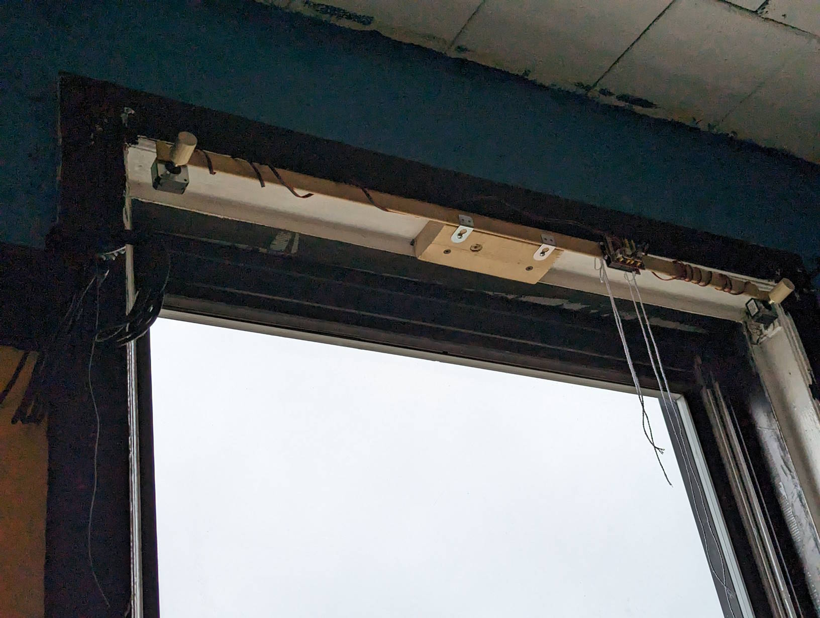
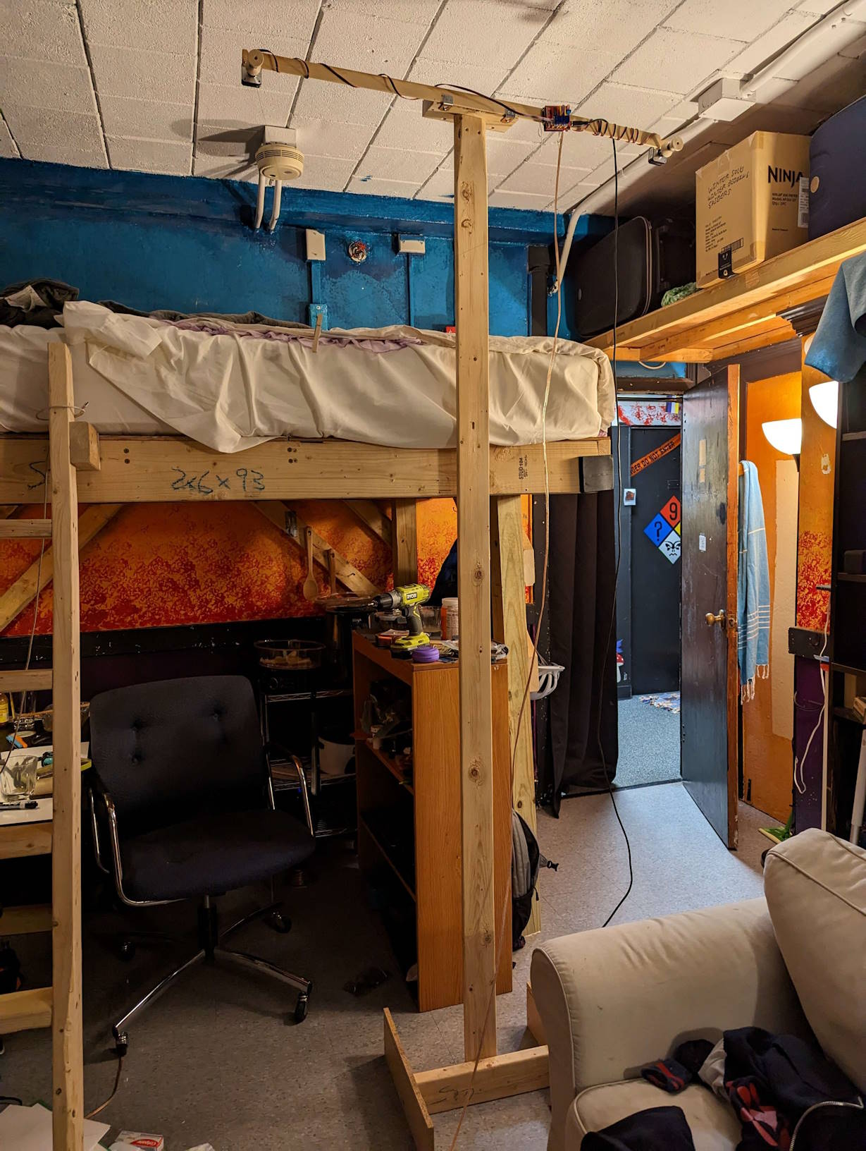
I used a thin piece of wood the length of my window as the body for my system (I think it used to be the rib for an old dorm window blind). I screwed in a stepper motor to each end of the body and tied an Arduino and CNC shield set near the middle. On each stepper motor I attached a spool with black thread, since I needed a string that was both unobtrusive and that I could fit 70 inches of around the spool.
I fix the system in place using a mount system, where the body sits on two brackets screwed into a 2x4 using my two favorite fasteners (gravity and friction). To facilitate development, I made one mount for the window (where the system is meant to be used) and one mount next to my desk (where it would be convenient to work with). The screwless system made it easy to move between the two.
For the blocker, I started out using a clothespin as a placeholder. I just needed some fixed point where the two strings connect so I could calibrate the system. Later, I used a small can lid, but runtime would probably demand either a bigger or fancier blocker (as per earlier reasoning). During exhibition, I used a very weighty Leatherman.
The choice of blockers affects whether we need active braking. In typical CNC systems, the stepper motors remain torqued during a job even when there’s no motion. This protects the system from movement that messes with the calibration. A drawback is that this torque generates heat and noise. Because the application of blocking the Sun requires only a very light blocker that moves very infrequently, I turned off active braking because the unpowered friction of the stepper motors was already enough to keep the blocker from moving. Then the motors are powered only when we need to move. This makes the system less distracting, which is what we want from a window blind system.
If we had a heavy blocker, like we do during exhibition, then we would need to turn active braking back on again. Otherwise, the blocker might fall to the ground as soon as movement stops. We also need to be careful to have the blocker resting on something when we power off the system so it doesn’t fall and break something or hurt someone.
Another choice I made during the development process was going from cheap motor drivers to microstepping drivers, as per an expert friend’s advice. Those moved a lot quieter. The microcontroller delegates some of the effort of controlling the stepper motors to these drivers, so the choice of circuit affects how the motors are driven.
During development, I kept the system connected to my laptop through a USB cable so I could input commands. But it could also just run scheduled tasks off DC power, which is how I would’ve set it up for a long-term deployment.
Exhibition
Because this project was (supposed to be) funded as a ProjXpo project, one request from the committee was that I present the project at the fair. This year, the xFair was hosted on the 6th floor of the MIT Media Lab in the second week of February.
Since my project was designed to be used in a very particular context (mounted on a window to block the Sun for a single viewer over the course of a day, moving inches per hour), I adapted it for exhibition so as not to bore the audience. To start, I built a small mount from my leftover wood to actually bring the robot over to my booth at the exhibition.
There was no point to showcasing the Sun blocking functionality, so when crunch time came, I started focusing on features that improved exhibition. For example, one of those things was the (partially failed) straight line movement, but others were features that we would’ve also used for blocking the Sun, like the scheduler.
With the scheduler, I wrote a routine in C++ to get the robot to trace all the regular polygons from 3 sides to 8 sides, then back again. I also upped the speed to as fast as my motors could reliably go. For the motion to be coherent, I clamped a Leatherman to the blocker for more inertia and turned on active braking.
Unfortunately, I didn’t have the foresight to take video at the exhibition (it was a long day preceded by a long night and long week) before disassembling it, so I’m afraid I can’t produce them here for you to see.
By the time the exhibition was over, I ran out of steam and reason to continue the project. It was already mid-February and the Sun angle was acceptably high so that glare was no longer an issue. Spring classes were starting, and I would not be living in this room the following year. So, I ended the project there.
I do still have the electronic parts, so if I ever needed to solve the same problem again, I can reassemble and reproduce the project. But that’s not in the foreseeable future.